
The Ultimate Guide: How Can I Protect My Building From a Lightning Strike?
A Complete Technical Guide to Lightning Protection Systems, Surge Protection Devices, and IEC 62305-Compliant Earthing Solutions
Did you know that a single bolt of lightning carries peak currents of up to 200 kA and can inject hundreds of megajoules of energy into a structure in microseconds? Despite this catastrophic potential, many facility managers and building owners vastly underestimate the engineering complexity required to properly protect a structure during a lightning storm. Every year, commercial buildings, industrial plants, data centers, and critical infrastructure across Lebanon suffer preventable damage, not from a lack of technology, but from inadequate or non-compliant protection systems. If you are asking yourself, “How can I protect my building from a lightning strike?”, you have come to the right place.
This exhaustive guide will break down the science of lightning, the exact engineering standards you must follow, and the expert-backed protection strategies necessary to keep your facility, personnel, and assets safe. Lightning is one of the most erratic and destructive natural phenomena on the planet. To engineer effective protection, you need more than a lightning rod on a rooftop, you need a fully coordinated system of air terminals, down conductors, earthing networks, equipotential bonding, and surge protection devices (SPDs). Let us dive deep into the ultimate protection framework.
Understanding the Anatomy and Threat of a Lightning Strike on Structures
Before you can effectively protect a structure, you must understand what you are designing against. A lightning storm is born from cumulonimbus clouds, where powerful updrafts and downdrafts cause ice particles and water droplets to collide at furious speeds. This friction creates a massive electrical charge separation. The top of the storm cloud becomes positively charged, while the lower portion becomes negatively charged. When the electrical potential difference between the cloud and the ground becomes too great, nature forcefully balances the equation with a lightning strike, discharging tens of thousands of amperes through whatever path it finds to earth.
IEC 62305: the international standard governing lightning protection, identifies the primary threat mechanisms that building protection engineers must account for. Understanding these is the foundation of any compliant Lightning Protection System (LPS) design:
- Direct Strike to the Structure
The most severe threat. A direct lightning attachment to the building injects the full lightning current into the structure. Without a dedicated air terminal network and down conductors, this current will seek any conductive path, steel reinforcement, electrical wiring, plumbing, causing catastrophic mechanical damage, fire, and injury to personnel through touch and step potentials.
- Strike Near the Structure
When lightning terminates on the ground near a facility, the current radiates outward through the soil. This creates dangerous step voltages across the earth surface and touch voltages on any ungrounded metallic structure connected to the ground. A properly designed earth termination system with equipotential bonding eliminates these gradients.
- Strike to Incoming Services (Conduction)
Lightning can couple onto incoming power lines, data cables, and telecommunications infrastructure and conduct the surge energy deep into a building. This is precisely why coordinated Surge Protection Devices (SPDs) — Type 1 at the service entrance, Type 2 at distribution panels, and Type 3 at sensitive equipment, are mandatory components of a complete protection strategy.
- Strike Near Incoming Services (Induction)
Even without a direct attachment, the intense electromagnetic field generated by a nearby lightning channel induces transient overvoltages in any conductive loop, power cables, data lines, control circuits. These induced surges are responsible for a significant proportion of equipment damage in facilities that have structural protection but lack coordinated SPDs and bonding.
- Direct Strike to a Connected Service
A lightning attachment to an overhead power line or exposed cable tray some distance from the facility will propagate the full impulse current along the conductor and into your electrical infrastructure. Type 1 SPDs with high impulse current ratings (10/350 μs waveform) are specifically engineered to handle this scenario at the point of service entry.
The External Lightning Protection System: Capturing and Conducting the Strike
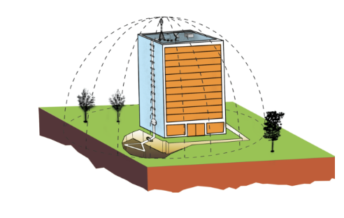
The External Lightning Protection System (LPS) is the first line of structural defense. Its purpose is to intercept the lightning attachment, conduct the full lightning current safely to ground, and dissipate the energy into the earth — all without allowing dangerous voltages to develop on the structure’s fabric, internal systems, or personnel. An external LPS consists of three tightly integrated subsystems, each engineered to IEC 62305 specifications.
Air Termination Network
The air termination network defines the strike capture zone. It consists of conventional lightning rods, catenary (horizontal) conductors, and mesh conductor grids positioned to intercept a downward stepped leader before it attaches to a vulnerable part of the structure. ZOD engineers apply the Rolling Sphere Method, the Protective Angle Method, and the Mesh Method, individually or in combination, based on the building’s geometry and its assigned Lightning Protection Level (LPL I through IV). Critical rooftop assets such as HVAC plant, photovoltaic arrays, antenna masts, and communication equipment require dedicated air terminal coverage to prevent direct attachment to unprotected equipment.
Down Conductors
Down conductors provide multiple parallel, low-impedance paths for the lightning current to travel from the air termination network to the earth termination system. Multiple symmetrically distributed down conductors are essential — they reduce the peak impedance seen by the current, minimize the magnetic field inside the building, and limit dangerous side-flash voltages that could bridge the gap to internal metalwork or personnel. IEC 62305 mandates strict calculation of the required separation distance between down conductors and internal conductive parts. Where this separation distance cannot be maintained architecturally, intentional equipotential bonding with appropriate SPDs must be implemented. All routing avoids sharp bends, minimizes loop areas, and is documented on as-built drawings with accessible test clamp positions.
Earth Termination System
The earth termination system is where the lightning current is finally dissipated safely into the mass of the earth. Its effectiveness is determined by the earth resistance value, which in turn depends on soil resistivity, a parameter that varies significantly by terrain and season. ZOD conducts soil resistivity testing using the Wenner 4-probe method before designing the earth electrode configuration. Ring earth electrodes, vertical driven rods, and horizontal radial conductors are deployed in combinations to achieve the required resistance values for the assigned protection class. All connections are made using exothermic welding or high-integrity compression clamps rated for the full impulse current, ensuring they remain reliable throughout the system’s service life.
How a Lightning Strike Is Managed by a Compliant LPS
Internal Lightning Protection: Bonding and Surge Protection Devices
Many facility managers assume that an external LPS alone constitutes complete protection. This is a critical and costly misconception. Even when the external system intercepts the strike perfectly, the enormous electromagnetic field generated by the flowing lightning current induces transient overvoltages in every electrical and electronic circuit inside the building. These induced surges, combined with any conducted energy from incoming services, are what destroy servers, PLCs, building management systems, medical equipment, and telecommunications infrastructure. The Internal Lightning Protection System: comprising equipotential bonding and coordinated SPDs, is non-negotiable.
Equipotential Bonding
Equipotential bonding is the process of interconnecting all separated conductive systems within a facility to a common reference potential, the Main Earthing Bar (MEB). This eliminates the dangerous voltage differences that would otherwise exist between the LPS down conductors, the structural steelwork, the electrical earth, the plumbing, the HVAC ducting, and the data cable trays during a lightning event. Without bonding, these potential differences cause destructive arcing between systems and lethal touch voltages on metallic surfaces throughout the building. All external services; power, gas, water, telecommunications, must be bonded at their point of entry using appropriate bonding conductors or, where direct bonding is not possible, through Type 1 SPDs.
Coordinated Surge Protection Devices (SPDs)
Surge Protection Devices are the final barrier between transient overvoltages and your electrical and electronic systems. ZOD designs and installs coordinated SPD networks compliant with IEC 61643 in a mandatory three-tier cascade architecture. Each tier handles a specific energy level and response time, and the coordination between them, including correct separation distances and decoupling inductance, is critical to their combined effectiveness.
Type 1 SPD: Lightning Current Arrester
Service Entrance / Main PanelInstalled at the main electrical service entrance. Specifically rated to handle partial lightning currents from direct strikes and high-energy surges conducted from overhead lines. Required by IEC 62305 whenever an external LPS is present. Rated to the 10/350 μs impulse waveform, the most demanding in the standard.
Type 2 SPD: Surge Arrester
Sub-Distribution BoardsPlaced at sub-distribution boards and distribution panels throughout the facility. Limits switching surges and residual energy not fully absorbed by the Type 1 device. The most widely deployed SPD type. Rated to the 8/20 μs impulse waveform. Protects distribution circuits, UPS systems, HVAC controllers, and elevator drives.
Type 3 SPD: Point-of-Use Device
At Sensitive EquipmentInstalled directly at sensitive loads; IT servers, PLCs, medical devices, laboratory instruments, and telecommunications equipment. Catches residual surges not fully attenuated by upstream SPDs. Low discharge capacity but extremely fast response time. Often integrated into equipment racks, sockets, or patch panels. Must never be used alone without upstream coordination.
The IEC 62305 Risk Assessment: Where Protection Design Begins
A compliant Lightning Protection System does not begin with product selection, it begins with a formal risk assessment per IEC 62305-2. This is the engineering process that objectively determines whether a facility requires lightning protection, what protection level is appropriate, and which combination of measures (external LPS, SPDs, shielding, and operational procedures) represents the most cost-effective solution. Skipping this step and simply installing a lightning rod is not compliant engineering, and may leave significant risks unaddressed.
The IEC 62305-2 risk assessment quantifies four types of loss: loss of human life, loss of service to the public, loss of cultural heritage, and economic loss. For each loss type, a tolerable risk threshold is established and compared against the calculated actual risk, which accounts for factors including the local lightning ground flash density (Ng), the physical dimensions and height of the structure, the nature of the soil and surrounding terrain, the type of construction and its fire risk classification, the occupancy and the criticality of the facility’s services, and whether incoming electrical and telecommunications services are overhead or underground. Where the calculated risk exceeds the tolerable level, a protection system must be designed to reduce it below that threshold. The output of this process is the required Lightning Protection Level (LPL), I, II, III, or IV, which directly governs the spacing of air terminals, the minimum conductor cross-sections, the earth resistance targets, and the SPD impulse ratings throughout the installation.
Debunking Common Lightning Protection Myths
Misinformation about lightning protection is alarmingly widespread, even among facility managers and building contractors. These misconceptions lead to non-compliant installations that provide a false sense of security while leaving real risks unaddressed. It is time to correct the record with engineering fact.
A single lightning rod on the rooftop is sufficient to protect the whole building.
✅ FACTA single rod protects only the area within its rolling sphere coverage zone — which varies by LPL but is never the entire building. IEC 62305 requires a complete air termination network designed using the Rolling Sphere, Protective Angle, or Mesh Method to ensure no part of the roof or structure falls outside the protected zone. Unprotected areas remain fully exposed to a direct attachment.
If the building has an LPS, the internal electrical equipment is automatically protected.
✅ FACTAn external LPS intercepts the direct strike, but the electromagnetic pulse it generates induces transient overvoltages on every electrical circuit inside the building. These induced surges, along with energy conducted from overhead power and data lines, will destroy sensitive equipment without a coordinated internal protection system comprising equipotential bonding and Type 1, 2, and 3 SPDs per IEC 61643.
A standard power strip surge protector provides adequate surge protection for critical equipment.
✅ FACTConsumer-grade power strips are designed for minor switching transients only. A lightning-induced surge — even a conducted partial lightning current — will instantly saturate and destroy a standard power strip while still delivering a damaging transient to the connected equipment. Proper protection requires IEC 61643-compliant SPDs in the correct Type 1/2/3 cascade, correctly rated for the impulse current levels at each installation point.
Once installed, a lightning protection system requires no further attention.
✅ FACTA lightning protection system is not a “fit and forget” installation. Soil conditions and moisture levels change with seasons, metal corrodes, mechanical fixings loosen, and SPD varistors degrade with each surge event. IEC 62305 mandates a schedule of periodic inspections, earth resistance re-testing using the Fall of Potential or clamp-on method, bonding continuity verification, and SPD status checks. A system that tested correctly at commissioning may be functionally compromised within a few years without proper maintenance.
Lightning Protection Across Industry Sectors
While the engineering principles of IEC 62305 are universal, their application varies significantly by facility type. The consequences of an unprotected strike — and therefore the required protection investment — differ dramatically between a commercial office building and a fuel storage facility or a hospital. ZOD engineers compliant systems across all of the following sectors, each with its own design considerations:
Commercial Buildings
Office complexes, hotels, shopping centers, and mixed-use developments. Primary concerns: personnel safety, continuity of IT and BMS systems, insurance compliance, and protection of building services including elevators and HVAC.
Industrial Facilities
Manufacturing plants, warehouses, and process facilities. Primary concerns: protection of automation controllers, variable speed drives, and process sensors from surges; prevention of fire from resistive heating or arcing in flammable environments.
Data Centers & IT Infrastructure
Mission-critical facilities. Requires the highest level of SPD coordination — robust mesh bonding networks, multiple parallel down conductors, shielded cable routing, and Type 1/2/3 SPDs on all power and data infrastructure to eliminate any risk of transient damage to servers and networking equipment.
Rooftop PV Arrays
Air terminals positioned clear of PV modules, bonding of all module frames and mounting rails, DC-side Type 1/2 SPDs at combiner boxes and inverter inputs, and AC-side SPDs at the inverter output. Careful routing of down conductors to maintain separation from DC cable runs.
Telecom Infrastructure
Base stations, masts, and antenna systems are inherently elevated and exposed, making them primary strike targets. Requires isolated mast earthing, coaxial SPDs on all antenna feeders, and coordinated protection on AC power and data backhaul lines.
Fuel & Chemical Storage
The highest-risk application. Requires isolated catenary or mast systems to eliminate any possibility of a direct strike on the tank, equipotential grading rings to suppress step voltage, and ignition-risk controls throughout. Zero tolerance for non-compliance.
Testing, Documentation, and Lifecycle Maintenance
A lightning protection system is only as reliable as its last verified test result. Soil conditions change seasonally, drought periods can dramatically increase earth resistance, rendering a previously compliant earthing system ineffective. Metal conductors corrode, mechanical fixings work loose under thermal cycling, SPD varistors degrade silently after each surge event, and roofing or renovation works frequently damage air termination networks without the damage being reported to the protection system owner.
ZOD provides comprehensive commissioning testing at project handover, including earth resistance measurement by the Fall of Potential method, down conductor continuity testing, bonding verification, and SPD functionality checks, with all results documented in formal test certificates. All project documentation including design calculations, protection class justification, as-built drawings with test point locations, and maintenance schedules is archived in ZOD360™, ZOD’s proprietary documentation platform, ensuring that records are always available for insurance audits, regulatory inspections, and future maintenance engineers. Periodic maintenance visits are scheduled based on facility risk classification, ensuring that the system’s performance remains verified and compliant throughout its operational life, not just at the moment of installation.